Beacon Mounting Location and Placement: BEEKs CM v2
Overview
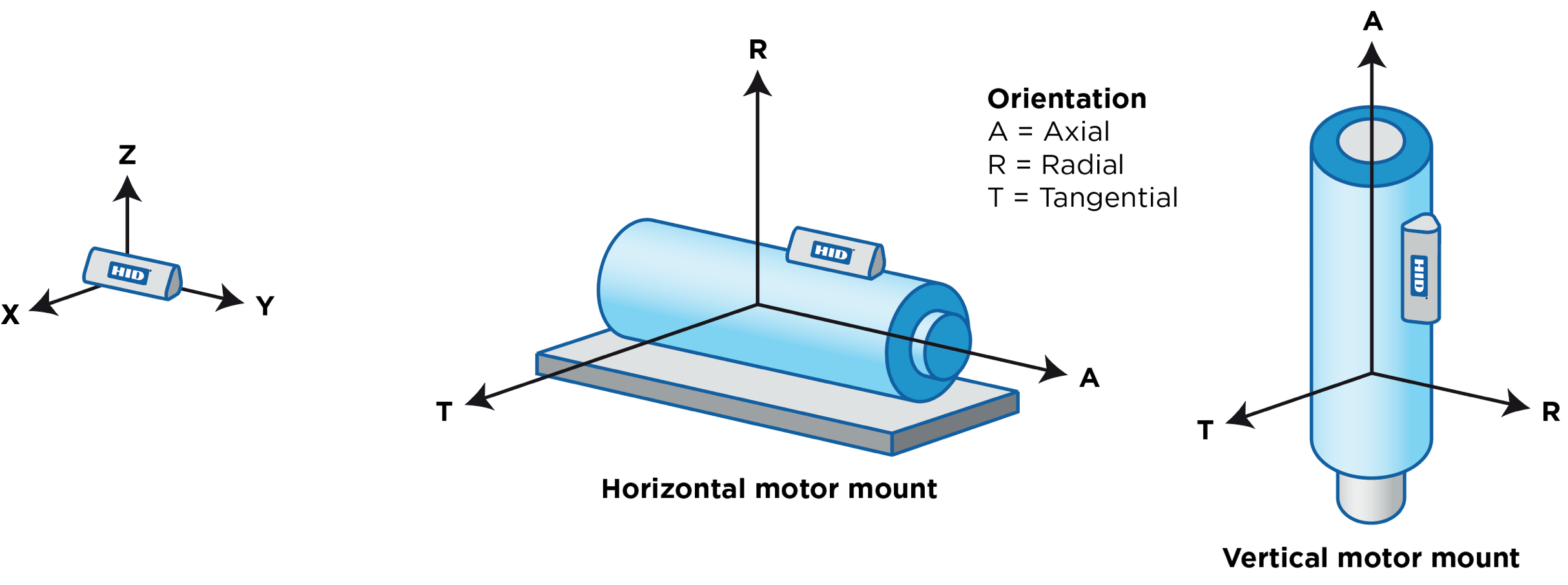
When installing BEEKs CM v2 beacons for vibration-based condition monitoring applications, it is important that each beacon be mounted on the asset at a location that optimizes the likelihood of detecting faults. The beacon should be mounted to a clean, flat, rigid surface close to the source of vibration. The three beacon axes (X, Y, Z) should be parallel to the three axes of the asset being monitored.
Beacons should NOT be mounted to flexible surfaces like metal enclosure walls, plastic motor fan covers, or junction boxes, as these will typically result in additional vibration that can distort the measurement signal. Cooling fins should also be avoided in general. Although most cooling fins appear rigid (do not visibly deform under pressure), they typically have a cantilever beam ("diving board") effect, in which they amplify vibrations at specific frequencies, which can cause distortion in the measured signal.
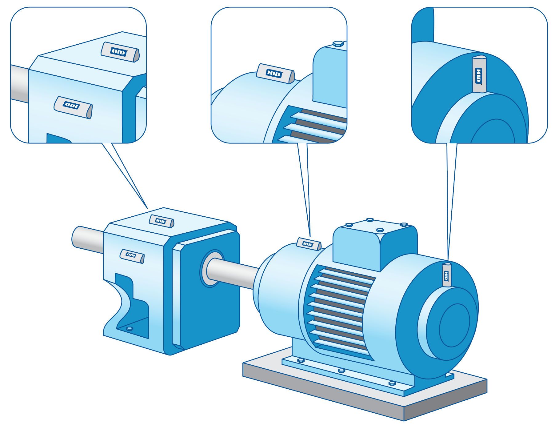
For larger assets or assets consisting of multiple pieces of machinery, multiple beacons should be used. For example, if a large motor is connected to a gearbox, one beacon should monitor the motor drive end, one beacon should monitor the motor non-drive end, and one beacon should monitor the gearbox. For larger gearboxes or gearboxes where the input and output shaft are oriented at 90 degrees to one another, it may be best to use two beacons.
Example Mounting Locations
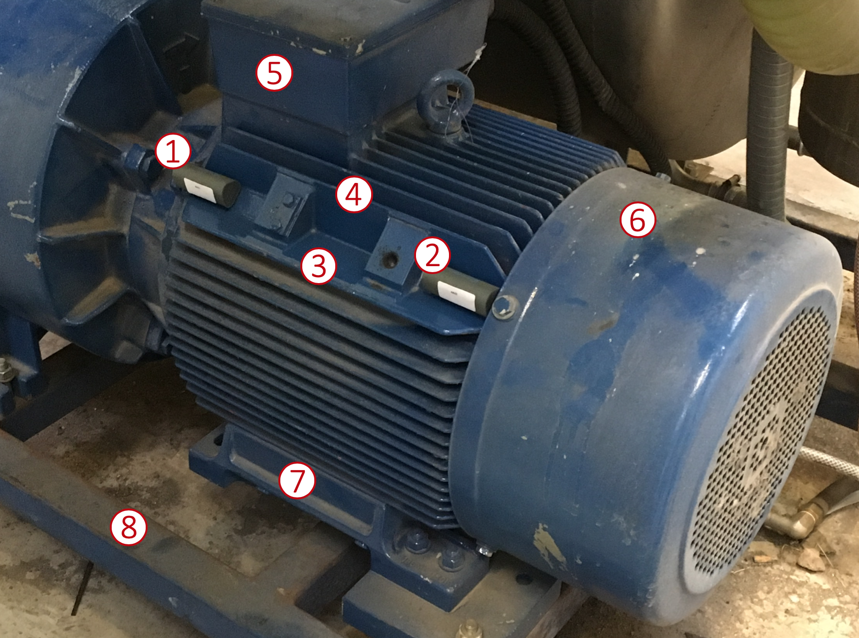
The following photo shows beacons installed on an AC induction motor. The image is annotated with numbers, with each of the locations explained below.
1: This is a good mounting location for the beacon to monitor the drive end of the motor. The beacon is mounted to a rigid part of the motor housing. The beacon Z-axis is oriented with the motor radial direction, the beacon Y-axis is oriented with the motor axial direction, and the beacon X-axis is oriented with the mounting surface tangential direction. Take note that the beacon is mounted in an area between the horizontal (3) and vertical (4) cooling fins, and not on the fins themselves. This surface is at a 45 degree angle, however, this does not cause a problem since the beacon axes remain properly oriented with the motor axes.
- 2: The same explanation for location 1 applies here. This is a good mounting location. This second location is also necessary to monitor the non-drive end of the motor.
- 3: The horizontal cooling fin is a poor mounting location, as it can cause increased vibration distortion at specific frequencies.
- 4: The vertical cooling fin is a poor mounting location, as it can cause increased vibration distortion at specific frequencies.
- 5: The junction box is a poor mounting location and should be avoided, as the box itself could cause vibration distortion at specific frequencies.
- 6: The fan cover is a poor mounting location and should be avoided. Although the cover is metal and is fastened to the housing of the motor, the cover is not supported fully, which can caused increased vibration distortion at specific frequencies.
- 7: The base of the motor is not a preferred mounting location. Although it is rigid, it is farther from the source of vibration than 1 and 2. However, if this motor were smaller and locations 1 and 2 were not possible, with the base being the only possible area for mounting, then location 7 might be a necessary compromise.
- 8: The frame that supports the motor is a poor mounting location and should be avoided, as it is far from the source of vibration and can cause vibration distortion at specific frequencies.


