Motion Condition Configuration
- Lutz Hennig
- Sarfraz Akram
This page provides an overview of the beacon configuration settings that are required in order to setup a beacon for Condition Monitoring in Bluzone.
Note:
Condition Monitoring settings are only supported by BEEKs Industrial and BEEKs Condition Monitoring beacons with a firmware revision of 405 or greater.
Overview
All Bluvision Condition Monitoring beacons are equipped with a 3-axis accelerometer that can sample acceleration at up to 800Hz. Condition Monitoring in Bluzone is mainly based on the data that is produced by that acceleration sensor.
If configured to do so, the beacons will continuously collect raw acceleration samples and aggregate them into a set of selected output features. Those features are computed by the beacon on-the-edge and then broadcast as BLE advertisements. Finally, the generated advertisements are picked up by BluFi devices within range of the beacon and transferred to the Bluzone Cloud.
Bluzone offers a wide variety of configuration settings in order to allow full customization of the generated Condition Monitoring features. The below sections will walk through each of the available configuration settings and provide details as needed.
Beacon Configuration Options
There are two options for configuring a beacon in the Bluzone Console.
Beacon Templates
Beacon Templates hold a set of configuration settings that can be applied to any compatible beacon. You can open and edit Beacon Templates by navigating to the appropriate section in the Bluzone Console as seen below.
Templates that are available in your project by default are system created and can not be edited. If you wish to use a template with custom settings, we recommend that you open and clone an existing template. The newly created clone can then be customized.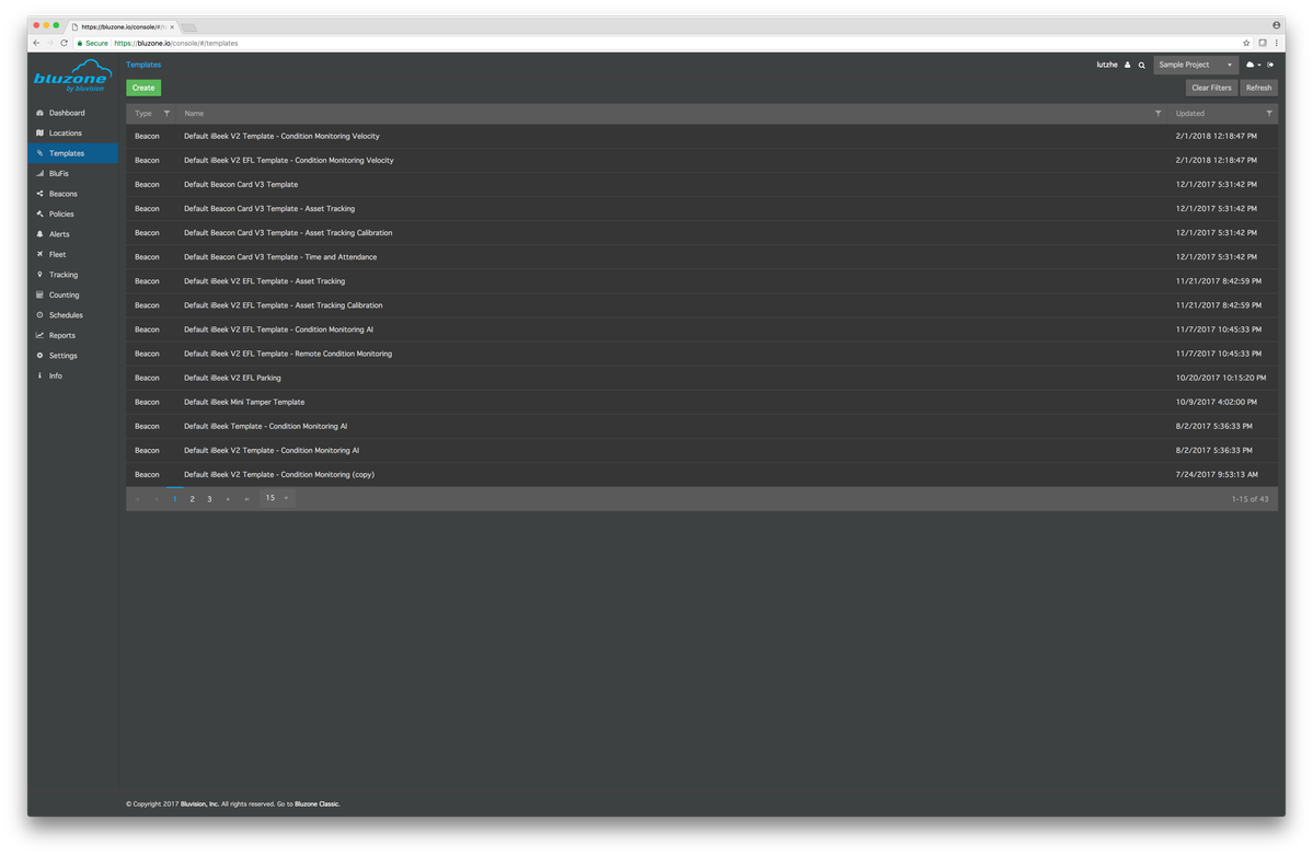
Beacon Configuration
The configuration of each beacon in a Bluzone project can be edited individually. In order to do that, please navigate to the appropriate beacon (Beacons > Select Beacon) and open its Configuration tab.
Condition Monitoring Configuration
When opening either a beacon or a template configuration you will see a configuration page similar to the one in the screenshot below.
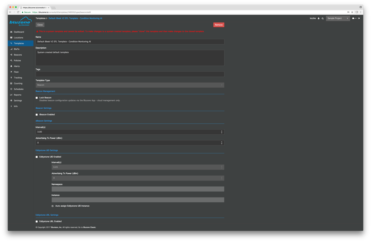
To view the Condition Monitoring configuration, please scroll all the way down until you see a section named "Motion Condition Monitoring". The following sections will cover each of the settings available in this part of the beacon and template configuration.
Enable Data Fountain Advertisements
In order to ensure that a beacon's produced Condition Monitoring features are synced with the Bluzone Cloud in a secure and redundant fashion, the output information is advertised by the beacon in an encoded packet type that we call "Data Fountain". Packets of this type are continuously produced by a Condition Monitoring beacon and are decoded in the Cloud in order to extract the contained features.
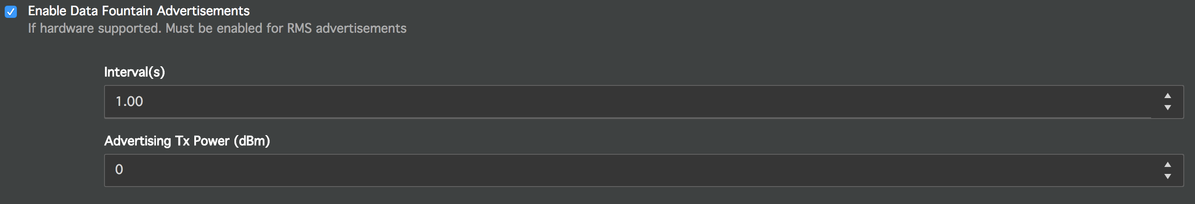
If you wish to enable Condition Monitoring on your beacons, you need to enable Data Fountain Advertisements by ticking the appropriate checkbox in the Bluzone Console as seen below.
In addition and just like for any other beacon advertisement type, the configuration of Data Fountain packets allows you to specify the rate / interval at which packets should be produced as well as their output power.
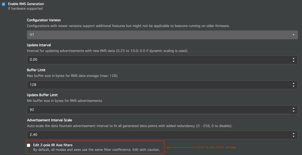
Enable RMS Generation
This is the second mandatory checkbox that you need to enable in any case if you want to enable Condition Monitoring features on your beacon.
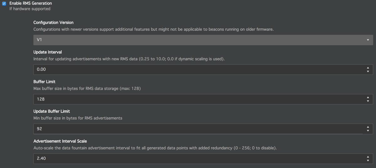
Configuration Version
This field indicates the version of the Condition Monitoring configuration of the given beacon or template. Different versions reflect the different capabilities of the available beacon firmware revisions. For this reason the configuration version of a beacon will always be non-editable as long as the beacon's firmware version does not change. At the same time, the version of a template can be selected.
Note:
While Bluzone will convert between configuration versions to a certain extent it is not recommend to apply a beacon template to a beacon with a lower configuration version. The beacon might not support certain features that are configured in such a template.
The currently available configuration versions are:
- V1
Used for beacons with firmware revisions between 405 and 410. Limited to acceleration-based output features. - V2
Used for beacons with firmware revisions above or equal to 412. Can generate velocity based features.
Output Buffer Configuration
In order to store and broadcast collected feature values, the beacon will keep 2 internal data buffers.
- Output buffer
This buffer holds the feature values that are currently advertised by the beacon. - Data buffer
This buffer holds the feature values that have recently been collected by the beacon.
When a beacon's data buffer is filled to capacity (Buffer Limit) or exceeds a specific size (Update Buffer Limit), its contents are rolled over into the output buffer. At this point the previous data in the output buffer will be deleted and the data buffer will be cleared. The beacon will continue collecting new feature values in the data buffer while broadcasting the new contents of the output buffer.
Optionally you can also set an Update Interval that will force a buffer rollover based on the defined interval in seconds (e.g. once every 5 seconds / 5.0).
The information that the beacon advertises can only be decoded by the receiver (Bluzone Cloud) if the full contents of the output buffer have been transmitted via Data Fountain packets. It is therefore important to ensure a certain level of advertisement redundancy. This is achieved by selecting a high enough broadcast rate for Data Fountain advertisements.
For example:
One Data Fountain packet has a size of 16 bytes. To fully transmit a 128 byte output buffer, at least 8 packets need to be transmitted. If the beacon broadcasts Data Fountain packets once per second it would therefore require at least 8 seconds in order to sync all of its data. If the beacon fills and updates its internal buffers within less than that amount of time, Bluzone will receive incomplete data sets and won't be able to decode the contained feature values.
The correct combination of an Update Interval and a Data Fountain broadcast interval depends on the selected Update Buffer Limit but also on the selected output features and feature calculation intervals. Please find more details about feature generation in the appropriate sections below.
Since manually calculating the required output rate of a beacon can be rather sophisticated the beacon allows you to specify an Advertisement Interval Scale parameter instead. If this parameter is set, the beacon's firmware will take care of automatically scaling the beacon's Data Fountain broadcast rate to a value that allows the beacon to broadcast all of the beacon's collected output data. The manually selected Data Fountain broadcast rate will then be overwritten by the beacon internally. The value of the Advertisement Interval Scale represents the redundancy factor of generated advertisements. The value in the screenshot below (2.40) would ensure that the beacon produces the required amount of packets multiplied by a factor of 2.4.
Filter Configuration
Raw acceleration data that is collected in order to generate feature values on the beacon can be filtered - e.g. in order to extract the desired frequency components. Bluzone's default templates for Condition Monitoring come with a default filter configuration that should work in most use cases. All of the available filters can however be fully adapted in order to use custom settings.
The filter configuration is by default not visible in the Bluzone Console. These are expert settings that can be adjusted after clicking the appropriate checkbox in a Beacon's or Tempate's configuration settings.
There are 2 individual filters for each acceleration axis of a beacon. As a result there is a total of 6 filters that can be configured on each beacon:
- X Axis Filter 1
- Y Axis Filter 1
- Z Axis Filter 1
- X Axis Filter 2
- Y Axis Filter 2
- Z Axis Filter 2
Filters 1 and 2 for each axis have a different purpose depending on which configuration version you are working with:
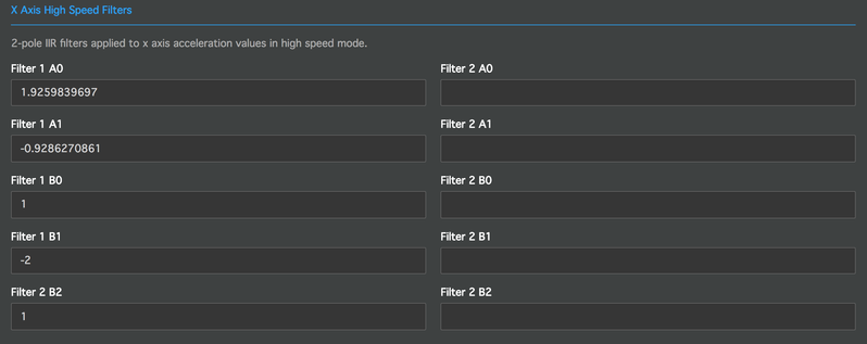
- V1 Configurations
Uses filter 1 in low speed mode and filter 2 in high speed mode. For details about beacon modes, please see the appropriate section below.
The screenshots below show the low speed and high speed filter configurations for a beacon's X acceleration axis as it will be visible for V1 configurations.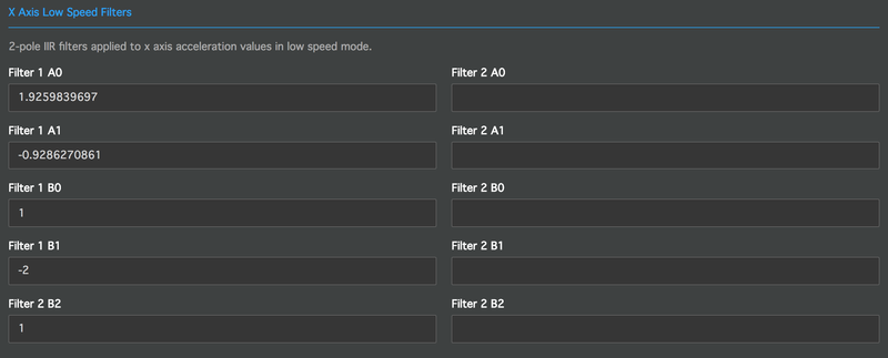
- V2 Configurations
The output of filter 1 is used to calculate acceleration based features in both low and high speed mode.
The output of filter 2 is used to convert raw acceleration into velocity in both low and high speed mode.
The below screenshots show the acceleration and velocity filter configurations for a beacon's X acceleration axis as it will be visible for V2 configurations.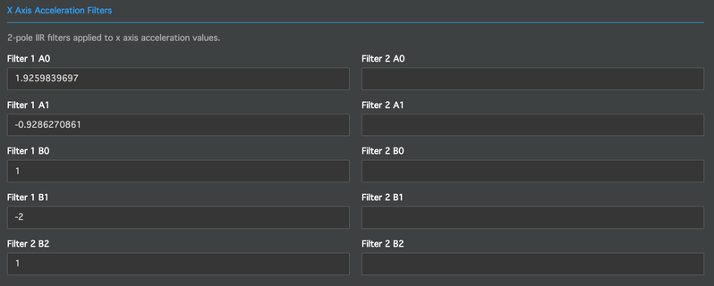
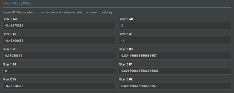
Each of the 6 available filters consists of 2 normalized Digital Biquad Filter sections. Raw acceleration data will flow into the first of these sections and get filtered based on its coefficients. The output of the first filter section will then flow into the second filter section. The output of the second filter section will then be collected and aggregated into the desired output features of the beacon. Therefore the coefficients that can be configured for each of the 6 beacon filters are the following (as seen in screenshots above):
- Filter 1 B0
- Filter 1 B1
- Filter 1 B2
- Filter 1 A0
- Filter 1 A1
- Filter 2 B0
- Filter 2 B1
- Filter 2 B2
- Filter 2 A0
- Filter 2 A1
Note:
We do not recommend that end users manually alter filter settings unless they are familiar with the underlying principles and/or have professional experience in this field. Altering filter settings can lead to unwanted results in a beacon's output values.
Low Speed and High Speed Configuration
When producing Condition Monitoring features, a beacon will continuously switch between 2 states of operation:
- Low Speed Mode
- High Speed Mode
Each of these modes individually defines ...
- ... which output features the beacon shall generate
- ... at which sampling rate raw acceleration data shall be collected
- ... how many collected samples shall be used to calculate one output data point
- ... when the beacon shall switch from the current state to the other one
The configuration parameters are equal for both a beacon's low speed and high speed mode. Please find a detailed description of the available per-mode settings below.
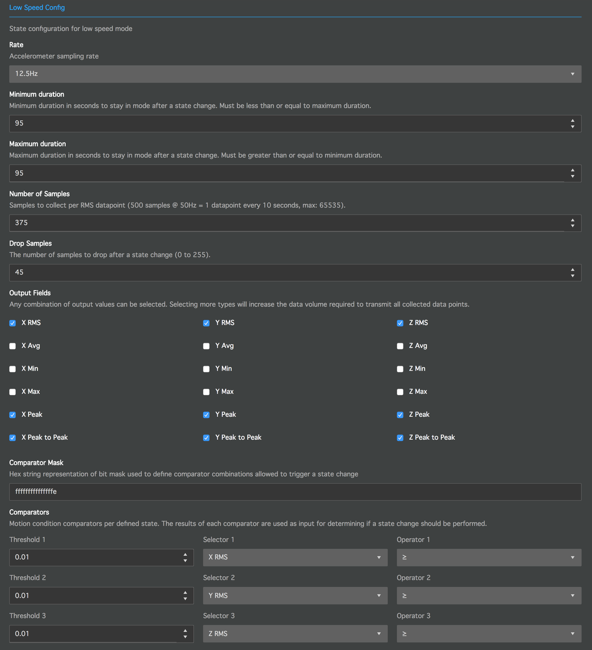
Rate
This parameter defines the accelerometer sampling rate for the given beacon state. It ranges between a minimum value of 1.56Hz and a maximum of 800Hz.
Minimum Duration
Defines the minimum duration to remain in the current mode after a mode switch.
For example:
If the beacon just switched from Low Speed into High Speed mode and High Speed mode defines a minimum duration of 10 seconds, the beacon will have to stay in High Speed mode for at least the next 10 seconds.
If the beacon just switched from Low Speed into High Speed mode and High Speed mode defines a minimum duration of 0 seconds, the beacon can switch back to Low Speed mode at any time.
Maximum Duration
Defines the maximum duration to remain in the current mode after a mode switch.
For example:
If the beacon just switched from Low Speed into High Speed mode and High Speed mode defines a maximum duration of 10 seconds, the beacon will have to switch back to Low Speed mode after 10 seconds or sooner.
If the beacon just switched from Low Speed into High Speed mode and High Speed mode defines a maximum duration of 0 seconds, the beacon remain in High Speed mode indefinitely.
Number of Samples
The number of raw acceleration samples used to calculate one data point for each output feature. If the selected sampling duration (defined by the sampling rate and number of samples) is longer than the given maximum duration, the sampling duration will override the maximum duration.
For example:
With a sampling rate of 800Hz and a number of samples of 8000, the beacon will collect accelerometer data for 10 seconds in order to collect one output data point. If the maximum duration for the current state is lower than 10 seconds, the beacon will still remain in this mode until it collected the full 8000 samples.
With a maximum duration of 15 seconds, the beacon would then collect data for 20 seconds since it would start a second sampling cycle after the first 10 seconds have passed.
Drop Samples
After the beacon switches between modes, different data filters might apply. In order to let the filtered values settle after a mode change you can specify this parameter. If specified, feature calculation and sampling will only start after a mode change after this amount of raw acceleration samples have been skipped.
Output Fields
The checkboxes in this section allows you to specify the features that the beacon shall calculate and advertise. Multiple output fields can be selected at once.
Selecting multiple output fields will increase the size of each output entry and thereby increase the rate at which the beacon's output buffer has to be updated. More output data generally leads to a higher required advertisement rate and increased beacon battery drain.
Note:
There are differences between the available output fields for V1 and V2 configurations. Only V2 configurations allow you to enable Velocity based output fields.
Note 2:
When using Condition Monitoring Policies in Bluzone, High Speed mode needs to enable the output fields required by the given policy. Acceleration policies require at least RMS, Peak and Peak-to-Peak features on all 3 axes. Velocity policies only require Velocity RMS on all 3 axes.
Comparators and Comparator Mask
In addition to the minimum and maximum duration, a mode switch can be triggered by a comparison of a beacon's output data against a threshold.
For example:
You can define that a beacon switches from Low Speed into High Speed mode in case its X-Axis RMS value exceeds a value of 1.0g.
The beacon allows you to specify 6 independent Comparators to perform such comparisons. Each comparator will compare the specified output value against an individual threshold. The outcome of the comparison is collected in a binary value (1: threshold exceeded, 0: threshold not exceeded).
The output of all 6 comparators is then evaluated against the Comparator Mask value in order to determine whether or not the beacon can change modes. The Comparator Mask is a 64 bit mask in which each bit represents one possible combination of firing comparators.
For example:
If all 6 comparators detect that their thresholds are exceeded, each of their outputs will be "1". This leads to the following binary representation: 1 1 1 1 1 1.
This binary value can be converted into a decimal number with the value 63. This is the index of the bit that we need to flip in the Comparator Mask value.
If we only set the 63th bit of the mask, it will produce a hexadecimal value of 0x8000000000000000 (as used in the screenshot above).
With this mask, the beacon would only switch modes in case ALL of its comparators report that their thresholds were exceeded.
For example:
If the beacon should switch modes in the case that ONLY the 5th comparator has fired, the binary representation would be: 0 1 0 0 0 0.
This binary value can be converted into the decimal number 16. This means that the 16th bit in the resulting Comparator Mask needs to be flipped.
This results in a hexadecimal value of 0x10000. Because of the required formatting, you would have to input the following in Bluzone: 0000000000010000.
With this mask, the beacon would only switch states in case the 5th comparator - and no other - reports that its threshold was exceeded.
Note:
If you wish that a beacon switches states in case a specific comparator has fired - independent of the other comparators - your Comparator Mask has to flip each bit that represents a combination of comparators where your desired comparator is enabled.